

How TruePart works: evidence in, verified geometry out.
TruePart works by keeping reading a drawing apart from building a part. Reading produces evidence and questions. Only an approved, typed plan reaches the deterministic CAD engine, and the solid it builds is measured against the requirements it came from. The Technical Preview reads native vector PDFs of one part on one sheet and builds one part family: rectangular plates with a centered bore and a hole pattern. AI interpretation is not enabled.
Technical Preview · one part family live, complex drawings in development · Current public demo: deterministic drawing reader · AI-assisted interpretation: in evaluation, not enabled
- 7 stages, each one checkable
- 9 requirements read from the demo drawing
- 8 questions asked instead of a guess
Seven stages, each one checkable.
Drawing → source coverage → ambiguity resolution → approved specification → constrained typed CAD plan → deterministic execution → geometry verification.
Drawing
The source drawing: a mounting plate, native PDF.
Drawing · TP-S1-0003-00 rev A

Evidence · 17 text runs · 9 read
Approved plan
The typed CAD plan built as geometry (wireframe).
Typed CAD plan · truepart-plan-mounting-plate 0.2.2

- box
- plate outline and thickness
- fillet
- four vertical corner fillets
- hole
- through bore at the plate center
- hole
- 6 through holes, 3 per row, centered
Verified solid
The verified solid, checked against the approved requirements derived from the drawing.
B-rep solid · 80 × 70 × 12 mm
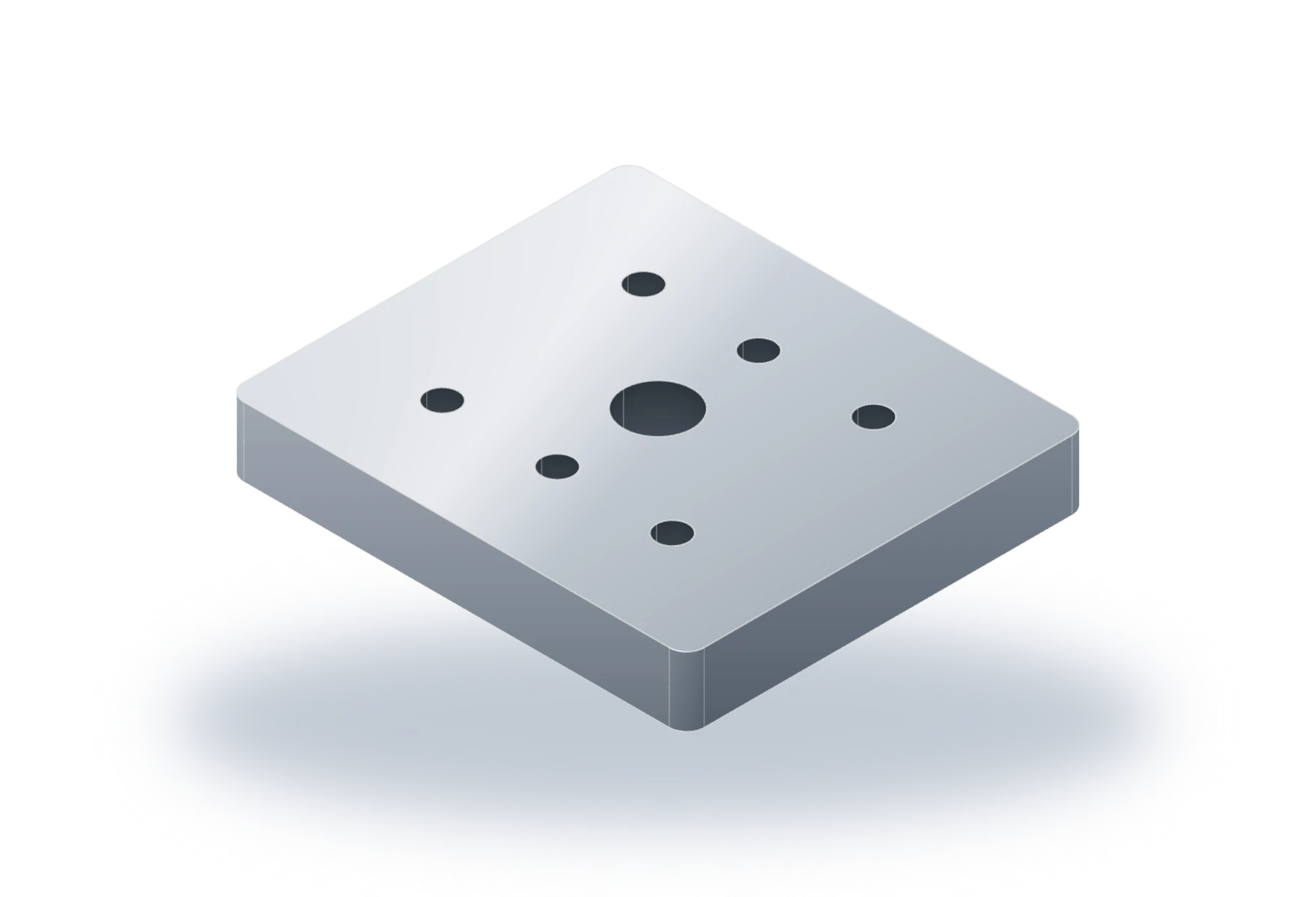
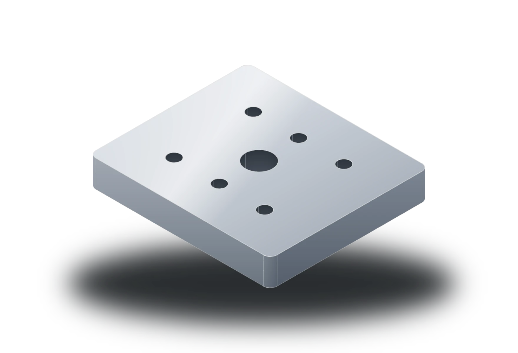
Measured against the specification before export
Drawing
A native PDF is ingested into pages, text runs with their positions, and a rendition, each with a hash. The drawing is the record everything later points back to.
Evidence
Source coverage
Every requirement carries the evidence it was read from: the callout, the title-block field, its box on the sheet. What the drawing does not state is visible as a gap, not filled in.
Evidence
Ambiguity resolution
Missing or ambiguous values become targeted questions. Nothing is built until they are answered; each answer is recorded with who gave it and, where possible, the text it cites.
Decision
Approved specification
The engineer reviews every requirement and approves a revision. Revisions are immutable: an answer or a correction creates a new one, and the one it replaces is kept.
Decision
Constrained, typed CAD plan
The approved specification becomes a typed CAD plan from a closed vocabulary of operations, validated for types, units, and references. It is data, never generated code.
Engine
Deterministic execution
A restricted interpreter executes the plan on an industrial B-rep CAD kernel. Only the validated plan crosses this boundary, and the same plan with the same software versions builds the same geometry.
Engine
Geometry verification
The solid is measured against requirement-level checks: envelope, feature counts, each hole’s position and diameter. STEP and STL ship with the record of what was checked and against what.
Engine
Models may interpret. Only the engine builds.
Interpretation
Uncertain, may ask.
Drawing interpretation is the uncertain step. Today a deterministic reader handles it for one part family; AI interpretation, when it is enabled, will sit behind a single provider boundary and return structured candidates, never geometry or code. Anything it cannot prove becomes a question.
Execution
Exact and deterministic.
Geometry execution must be exact. The CAD engine accepts only a validated, typed plan, executes it deterministically, and verifies the solid it built. Model output never reaches a code-execution path.
Every value knows where it came from.
- 01
Requirement-level trace. Callout → requirement → CAD feature → verification result, for every requirement the plan uses.
- 02
Controlled revision. Readings, answers and approvals each create a new specification revision; nothing is edited in place.
- 03
Reproducible builds. The plan, the interpreter and kernel versions, and the artifacts are recorded together, so a part can be rebuilt and re-checked.
- 04
Current limits. Verification covers what was captured. Tolerance bands are carried as data and the CAD is built at nominal; material and manufacturability are not checked yet.
Fifty complex test parts, in our evaluation corpus.
Each part is pictured as its drawing specifies it. Synthetic, company-owned test drawings, marked not for manufacture. None of these parts has been built by TruePart or made in a shop; the live pilot reads one part family today. No results on it are published yet.
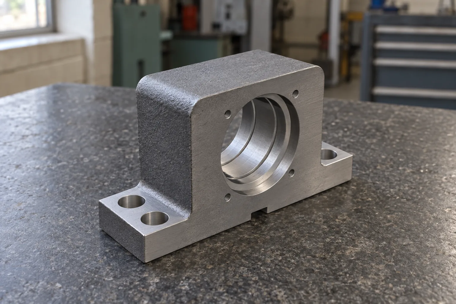
Pillow block bearing housing · TP-C006 · synthetic test part · 6 views with section A-A · internal geometry 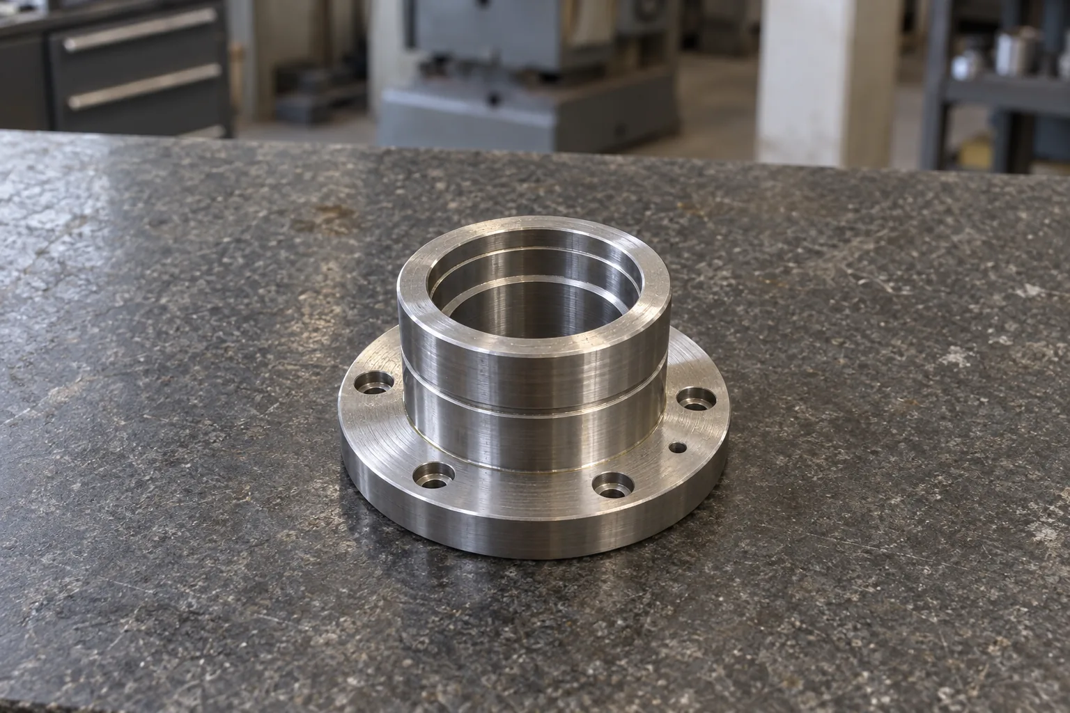
Flanged bearing cartridge · TP-C002 · synthetic test part · 7 views with section and detail · internal geometry 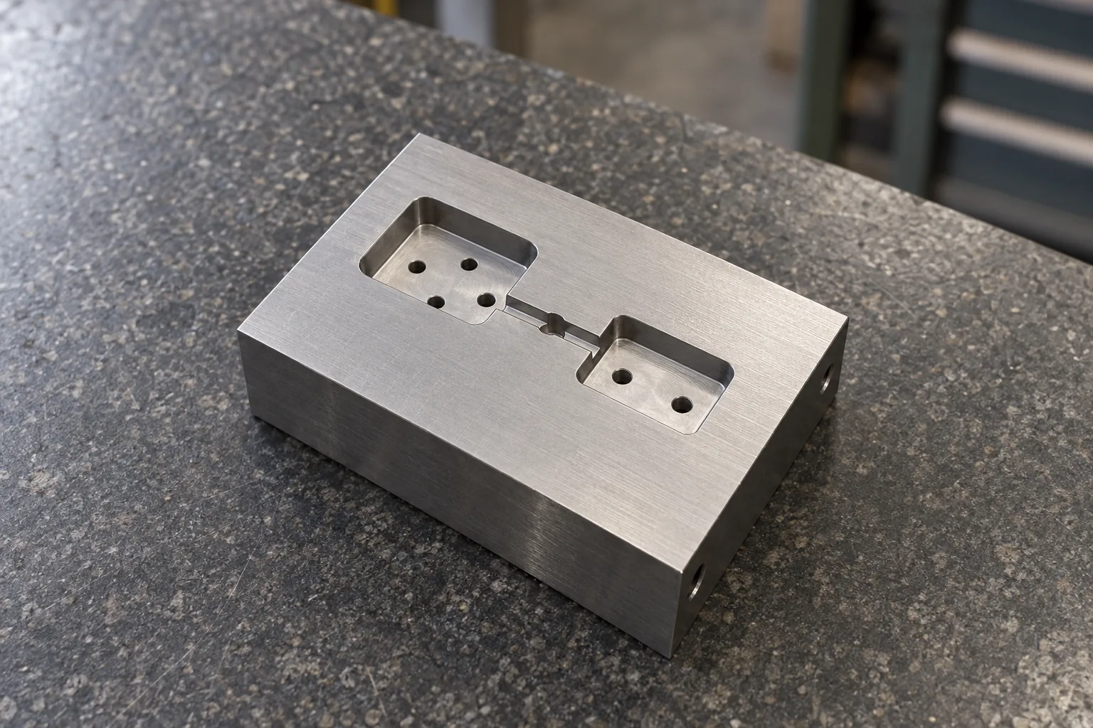
Two-cavity mould insert · TP-C032 · synthetic test part · 6 views with section A-A · non-inferable value 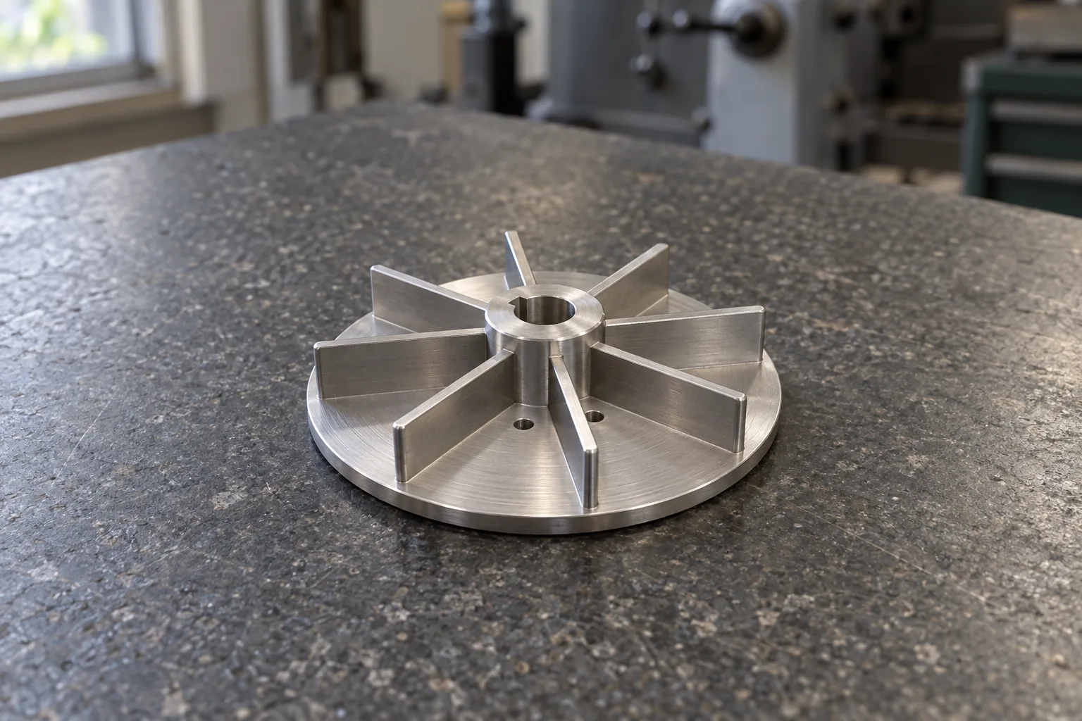
Open impeller · TP-C010 · synthetic test part · 6 views with section A-A · partial · a correct reader asks 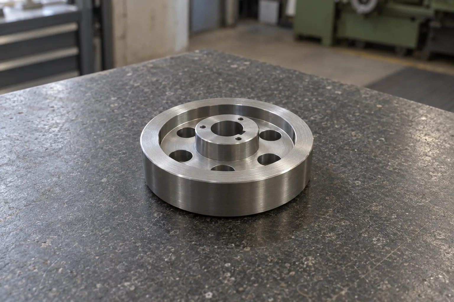
Lightened gear blank · TP-C049 · synthetic test part · 6 views with section A-A · missing dimension · a correct reader asks 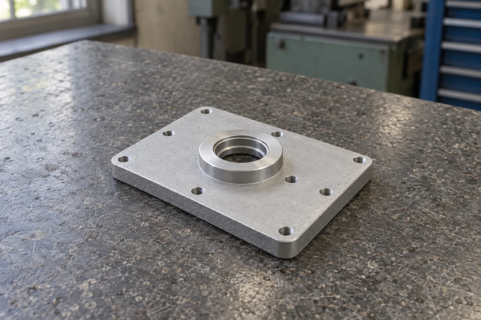
Gearbox cover with gasket groove · TP-C021 · synthetic test part · 7 views with section and detail · internal geometry · a correct reader reads it 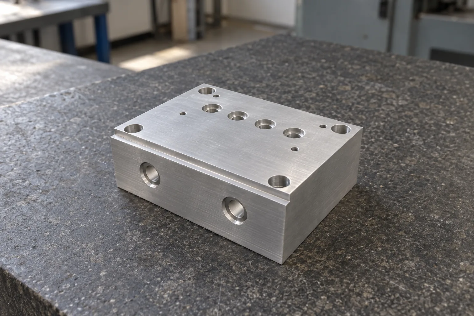
Ported gauge block · TP-C001 · synthetic test part · 6 views with section A-A · fully specified · a correct reader reads it 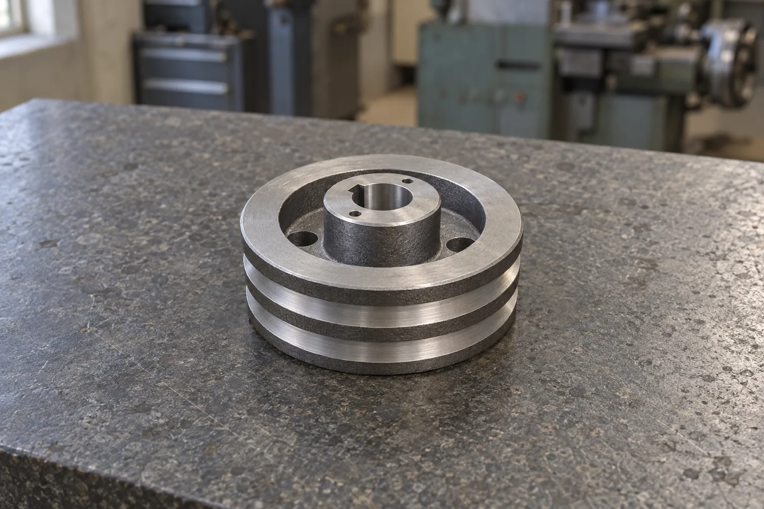
Two-groove V-belt pulley · TP-C013 · synthetic test part · 6 views with section A-A · ambiguous · a correct reader asks 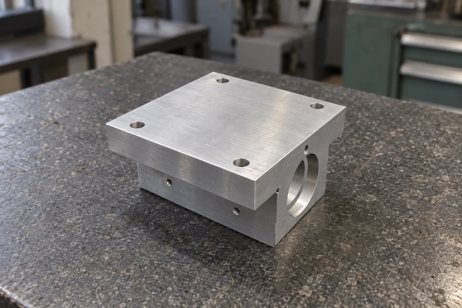
Linear bearing carriage block · TP-C018 · synthetic test part · 6 views with section A-A · several views · a correct reader reads it 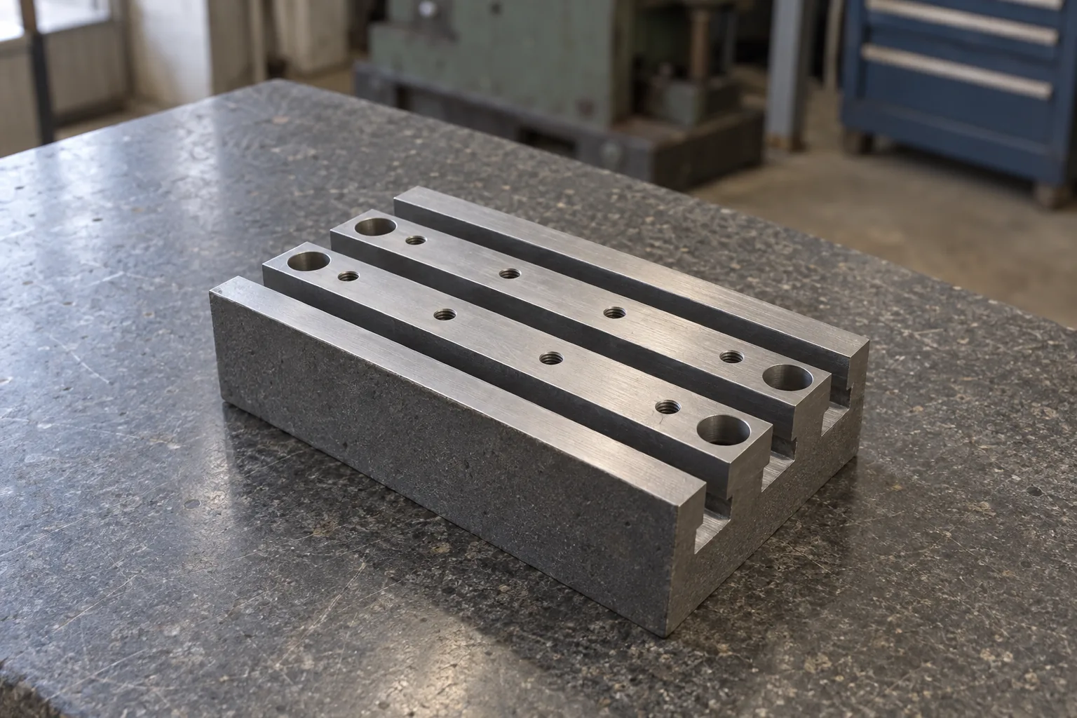
T-slot table segment · TP-C015 · synthetic test part · 5 views · several views · a correct reader reads it 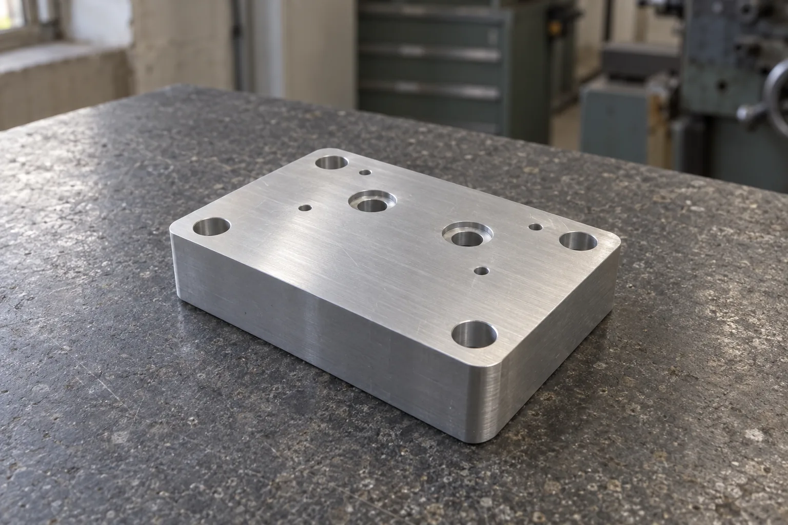
Offset port adapter plate · TP-C047 · synthetic test part · 6 views with section D-D · datums · a correct reader reads it 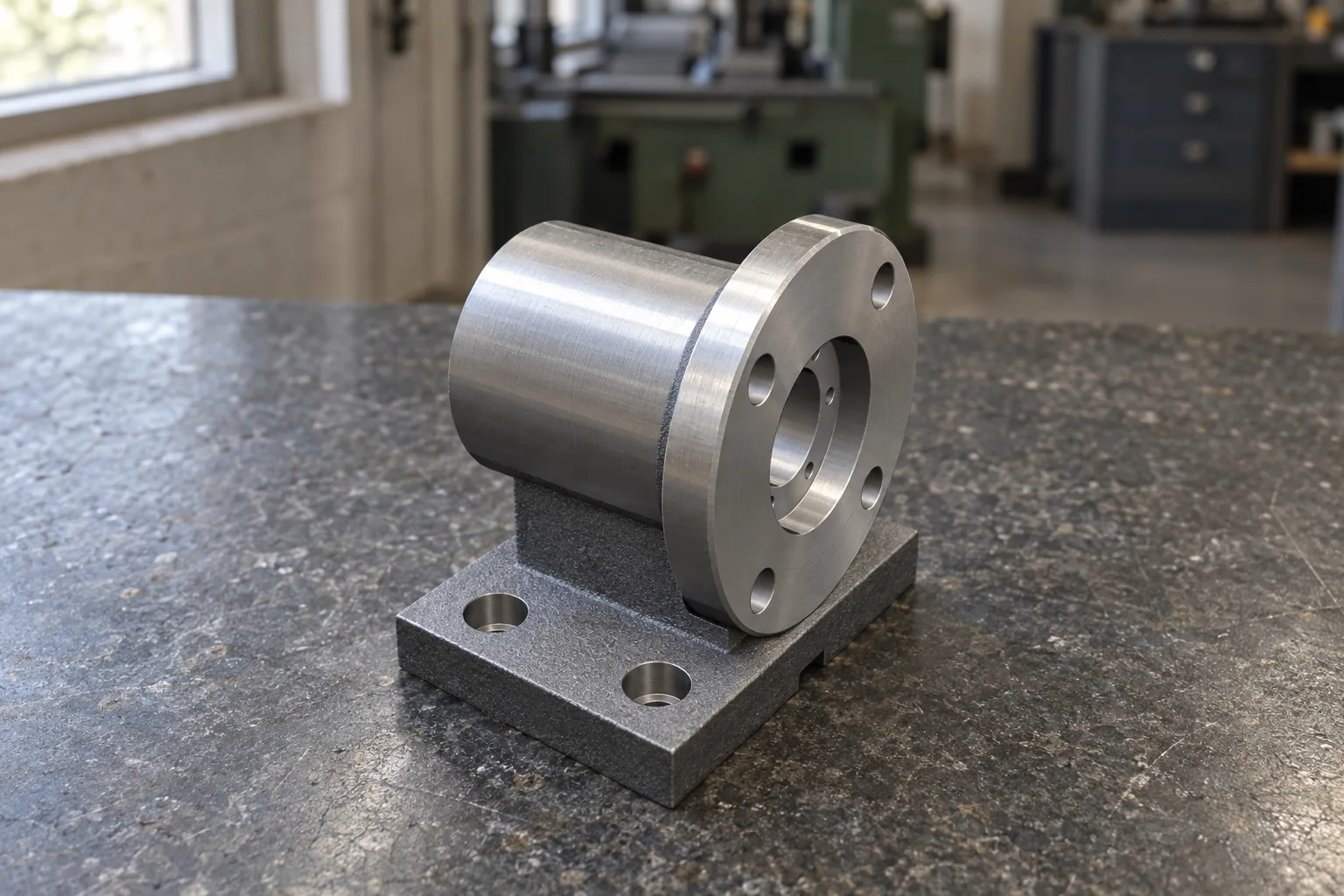
Lead screw nut housing · TP-C044 · synthetic test part · 6 views with section and detail · internal geometry · a correct reader reads it 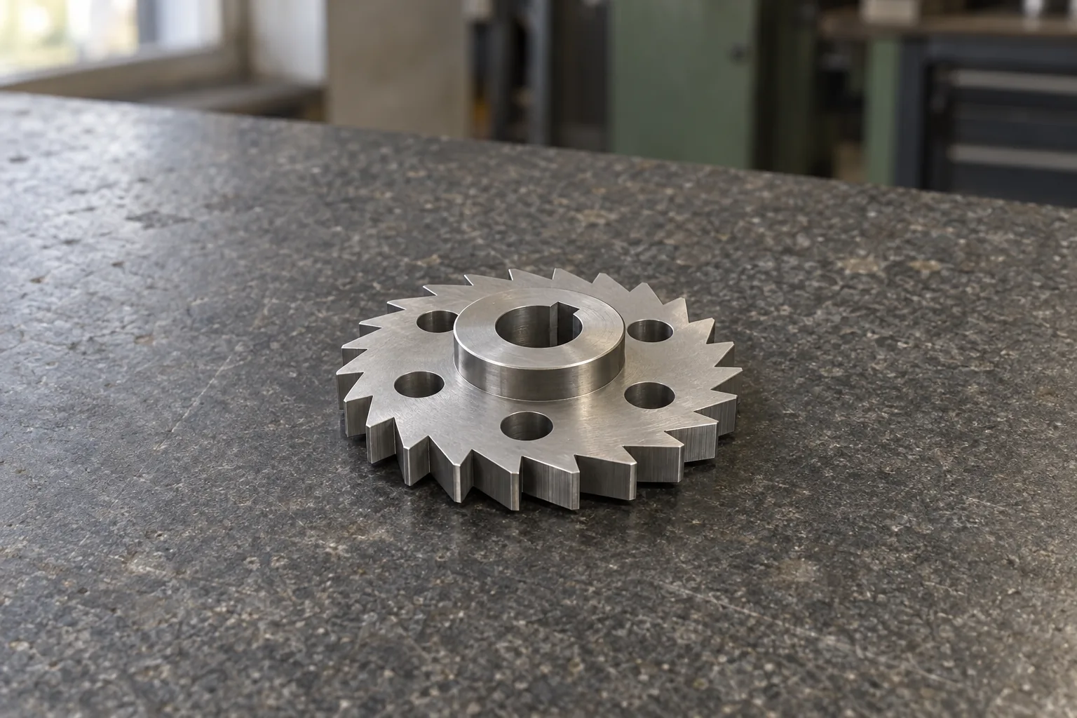
Ratchet wheel · TP-C036 · synthetic test part · 4 views · partial · a correct reader asks 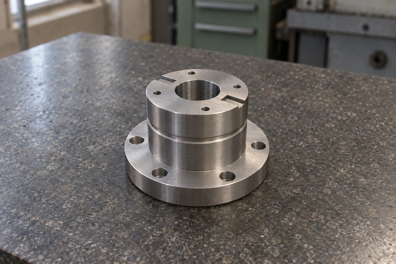
Spindle nose adapter · TP-C038 · synthetic test part · 7 views with section and detail · datums · a correct reader reads it
Patent Pending
Certain TruePart technologies relating to evidence-gated engineering workflows, deterministic CAD generation, requirement-level verification, provenance, and controlled revision are patent pending.
How TruePart works: the questions engineers ask.
How does TruePart work?
In seven stages, each one checkable: drawing → source coverage → ambiguity resolution → approved specification → constrained typed CAD plan → deterministic execution → geometry verification. Reading produces evidence and questions. Only an approved, typed plan reaches the deterministic CAD engine, and the solid it builds is measured against the requirements it came from.
Does TruePart use AI to read drawings?
Not today. Current public demo: deterministic drawing reader. AI-assisted interpretation: in evaluation, not enabled in this preview. When AI interpretation is enabled, it will sit behind a single provider boundary and return structured candidates, never geometry or code.
Does a model write the CAD geometry?
No. The approved specification becomes a typed CAD plan from a closed vocabulary of operations, validated for types, units, and references. It is data, never generated code. Model output never reaches a code-execution path.
What does verification check?
Verification measures the envelope, volume, hole count, and each hole’s position and diameter against the approved specification. It does not check tolerance bands, material or manufacturability, and a misread callout still needs your review. Tolerance bands are carried as data and the CAD is built at nominal.
Which parts can it build today?
One part family in the Technical Preview. It builds one family: a rectangular plate with one centered through bore and one centered rectangular pattern of through holes; sharp, chamfered or rounded corners. The input is a native vector PDF with a text layer: one sheet, one part, millimetres, up to 10 MB. Implemented, not enabled: a multi-view bracket path. A stepped bracket drawn in several views and a section, taken from a synthetic, company-authored drawing to a STEP file in internal tests, with the readers it uses. Internal only: customers cannot use it. In development: groundwork for complex part families. Work on open branches, starting with integrity fixes to the internal multi-view path. Each family is to be measured on held-out drawings before it is offered. No held-out results are published yet. Roadmap: complex part families. Family by family: a bracket or housing block with features on several faces, a turned flange, a stepped shaft and a bearing housing, with sections, diameters and datums read from the drawing. Planned, not built.
Further reading
See the architecture on a real drawing.
The home page follows a sample drawing through each stage. Pilot participants bring their own drawings.