

AI drawing to CAD, checked against the approved spec.
TruePart is AI CAD for engineering drawings. It turns a drawing into CAD: it reads the callouts and title block, asks about every value it cannot prove, builds a B-rep solid with a deterministic CAD engine, and measures it against the approved requirements. The Technical Preview reads native vector PDFs of one part on one sheet and builds one part family: rectangular plates with a centered bore and a hole pattern. AI interpretation is not enabled.
Technical Preview · one part family live, complex drawings in development · Current public demo: deterministic drawing reader · AI-assisted interpretation: in evaluation, not yet enabled · the demo uses a synthetic drawing
- 9 requirements read from the demo drawing
- 8 questions asked instead of a guess
- 17 text runs kept with their positions
From drawing to CAD, checked against the approved spec
Technical drawing · PDF
Drawing
A native vector PDF: one sheet, one part, in millimetres. Its text layer is kept with exact positions, so every value can point back to where it was written.
Drawing · TP-S1-0003-00 rev A

Evidence · 4 · Ø12 ±0.05 THRU
Requirements, read or asked
Understand
Callouts (Ø, fits, ±, THRU, threads, R, C) and title-block fields become requirements. Anything the reader cannot attribute becomes a question; on the demo drawing, 9 were read and 8 asked.
Requirements · 9 read · 8 asked
- Bore
- Ø12 ±0.05read
- Pattern
- 6 × Ø5.5read
- Material
- 6061-T6 ALUMINUMread
What is the plate thickness (shown in the side view)?
askedanswered 12 mm
Deterministic B-rep
Engineer
The approved specification becomes a typed plan. A deterministic engine executes it (no model writes geometry code), and each feature keeps the requirements it came from.
CAD model · 80 × 70 × 12 mm
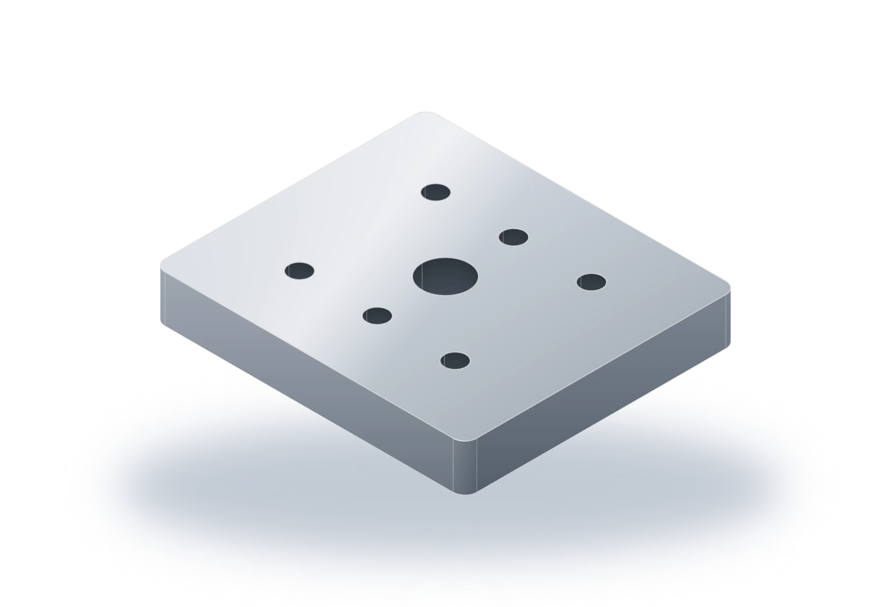
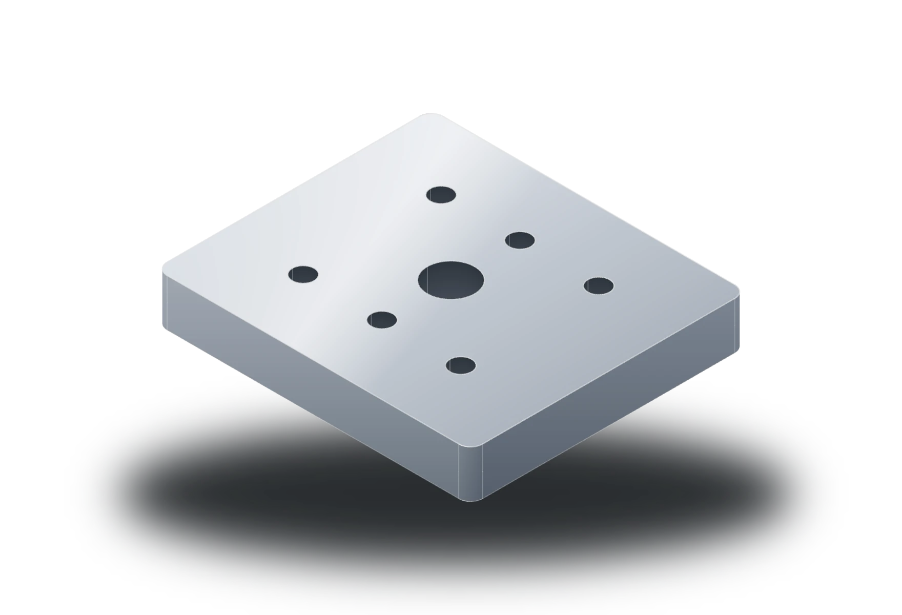
Feature · bore · through bore at the plate center
Measured against the spec
Verify
The solid is measured against the specification before STEP and STL are exported. Ordering and quoting are not available in this preview.
The checks
The built solid’s envelope, volume, hole count, and each hole’s position and diameter are measured against the approved specification. The results, check by check, are in the workspace.
A drawing already exists. Someone still rebuilds it.
It is skilled, repetitive work, and a single misread dimension becomes a scrapped part.
| By hand | In TruePart | |
|---|---|---|
| Reading | Every view is read and every dimension retyped into a CAD sketch. | Callouts and title-block fields are read from the PDF’s text layer, each with its place on the sheet. |
| Gaps | Where the drawing is silent, the modeler picks a value and the CAD looks just as certain. | A value the drawing does not prove becomes one question. Nothing is built until it is answered. |
| Building | Features are modeled by hand, one sketch at a time. | A deterministic engine builds the B-rep from a typed plan of the approved specification. |
| Checking | The model is checked against the drawing by eye, if there is time. | The solid is measured against the specification: envelope, volume, hole count, each hole’s position and diameter. |
Ask, don’t guess.
Where the drawing does not prove a value, TruePart asks one targeted question and builds nothing until it is answered. These are the demo drawing’s own questions.
What is the plate thickness (shown in the side view)?
Why it matters
Sets the extrusion depth; through holes depend on it.
askedanswered 12 mm
How many holes are in each row of the hole pattern?
Why it matters
The hole count alone does not fix the layout (6 holes can be 3 × 2 or 2 × 3).
askedanswered 3
Where is the bore located? No position dimension is written; the drawing shows centerlines.
Why it matters
Placing the bore needs its position; deriving it from centerlines needs vector geometry extraction, which is not built yet.
askedanswered centered (symmetric)
From callout to verified solid.
Reads the drawing
Diameter, thread, radius and chamfer callouts, hole patterns, and the title block, each linked to its source box.
Asks about the rest
Plain linear dimensions and positions shown only by centerlines become targeted questions, never guesses.
Builds and verifies
A deterministic engine executes a typed plan. No model writes geometry code. The solid is measured before export.
STEP and STL
The exact B-rep solid as STEP for CAD and CAM, and a mesh of the same solid as STL for printing.
Every value, from callout to verified geometry.
The bore of the demo drawing, followed through the pipeline: the callout it was read from, the requirement, the CAD feature, and what was measured on the solid.
Drawing callout
REQ 4 · Ø12 ±0.05 THRU · drawing TP-S1-0003-00 rev A
Ø12 ±0.05
Requirement · hole_1_diameter
- Requirement
- read from the drawing · confirmed by the reviewer
- CAD feature
- bore · through bore at the plate center
- Measured
- in the workspace
- Against
- the planned diameter and position
Verification measures the envelope, volume, hole count, and each hole’s position and diameter against the approved specification. It does not check tolerance bands, material or manufacturability, and a misread callout still needs your review.
What is live today, and what is not yet.
If TruePart cannot prove what the drawing means, it asks or stops instead of guessing.
Production-verified
- 01Native vector PDF with a text layer: one sheet, one part, millimetres, up to 10 MB
- 02Diameter callouts with a fit, ± or signed deviation, and THRU; NX hole patterns
- 03Thread (M), radius (R) and chamfer (C) callouts
- 04Title block: material, general tolerance, units
- 05Builds one family: a rectangular plate with one centered through bore and one centered rectangular pattern of through holes; sharp, chamfered or rounded corners
Not live yet
Stated apart from what is live: none of it is offered in this preview.
- 01Implemented, not enabled: a multi-view bracket path. A stepped bracket drawn in several views and a section, taken from a synthetic, company-authored drawing to a STEP file in internal tests, with the readers it uses. Internal only: customers cannot use it.
- 02In development: groundwork for complex part families. Work on open branches, starting with integrity fixes to the internal multi-view path. Each family is to be measured on held-out drawings before it is offered. No held-out results are published yet.
- 03Roadmap: complex part families. Family by family: a bracket or housing block with features on several faces, a turned flange, a stepped shaft and a bearing housing, with sections, diameters and datums read from the drawing. Planned, not built.
Not in this preview
- 01Scanned, raster or multi-sheet drawings (stopped: advanced interpretation required)
- 02Any other part shape: pockets, bosses, counterbores, sheet metal, assemblies (stopped: outside the current scope)
- 03GD&T frames and surface finish (not read yet)
- 04Checks of tolerance bands, material or manufacturability
- 05AI interpretation: built behind TruePart’s provider boundary, not yet run or enabled
- 06Text, photo or sketch input; ordering and quoting
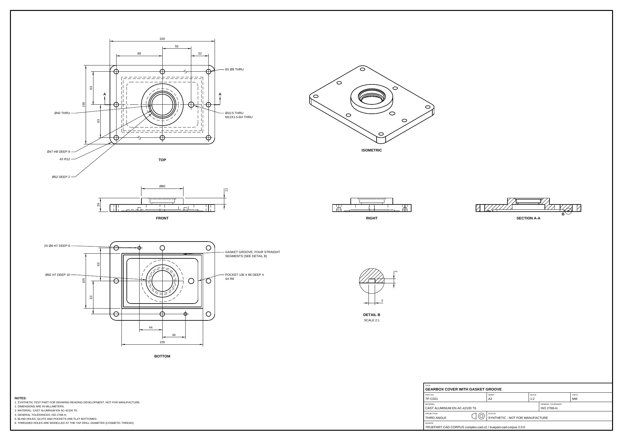
Fifty complex test parts, in our evaluation corpus.
Each part is pictured as its drawing specifies it. Synthetic, company-owned test drawings, marked not for manufacture. None of these parts has been built by TruePart or made in a shop; the live pilot reads one part family today. No results on it are published yet.
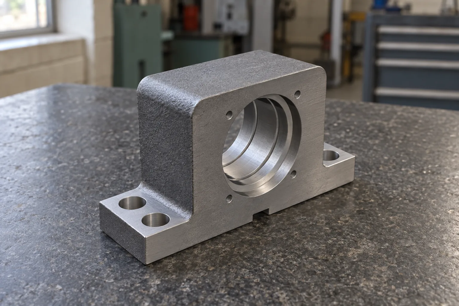
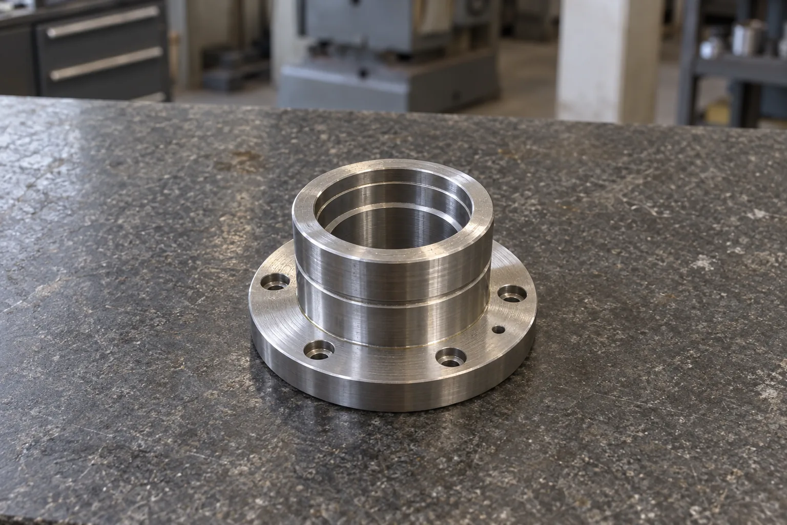
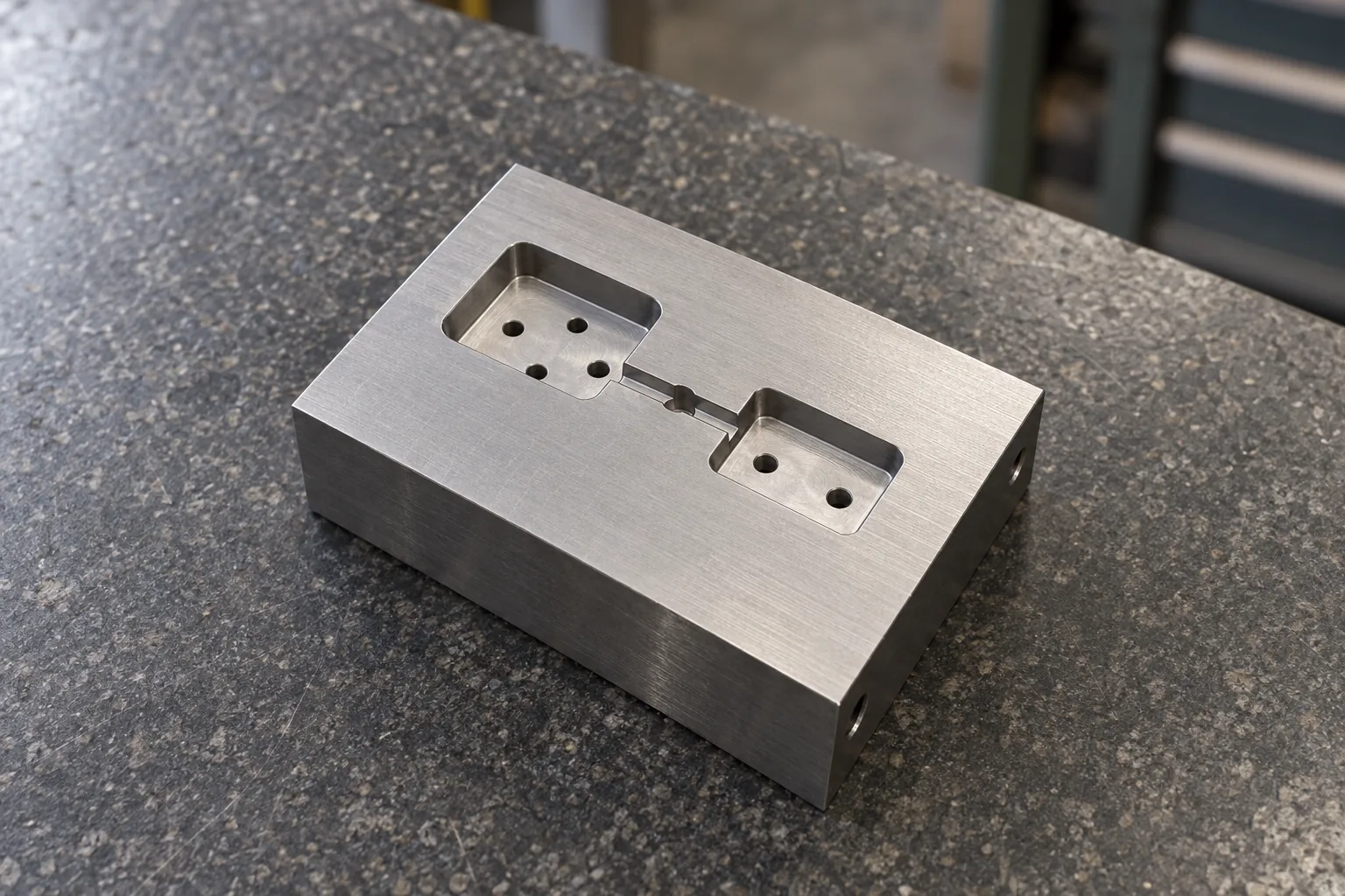
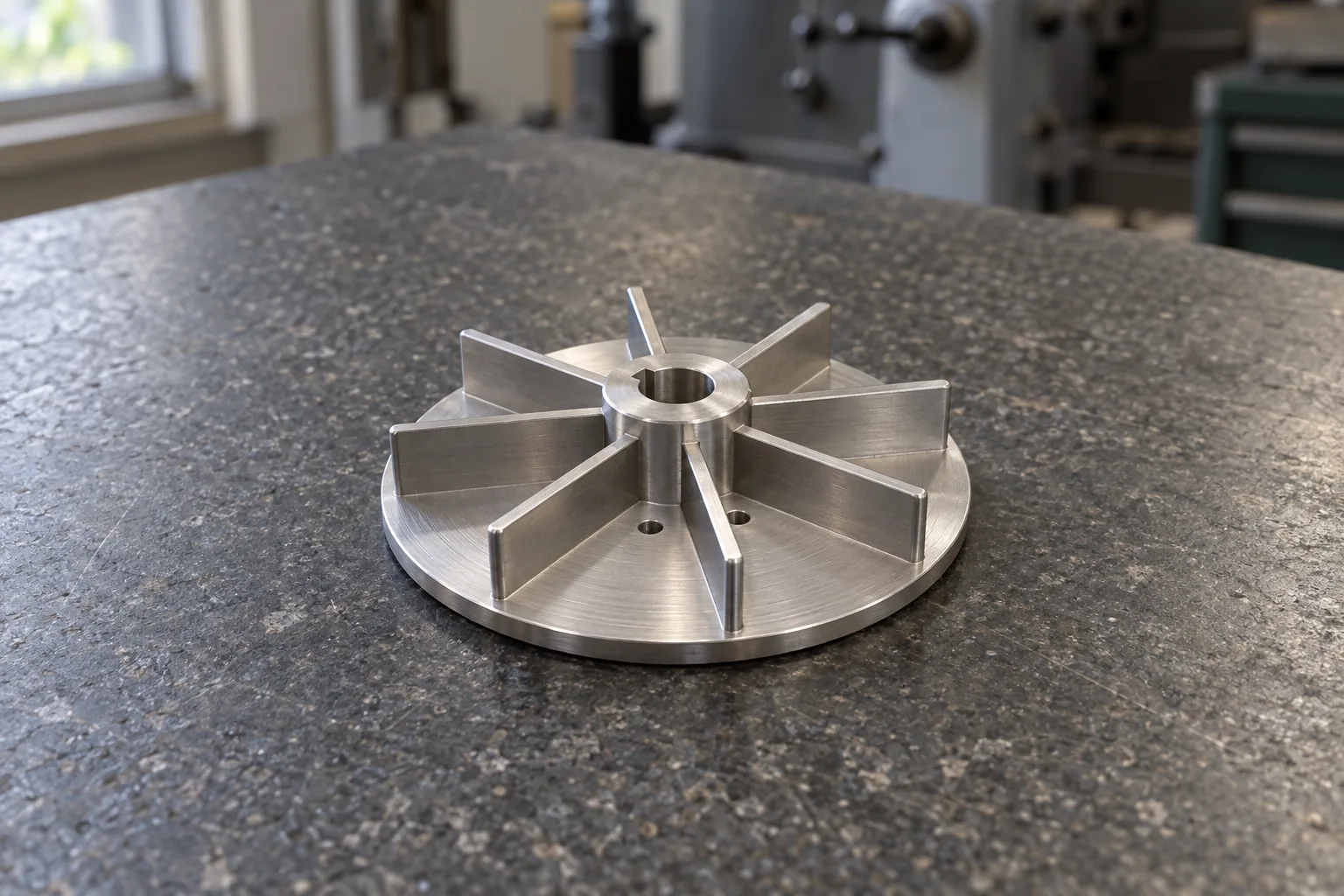
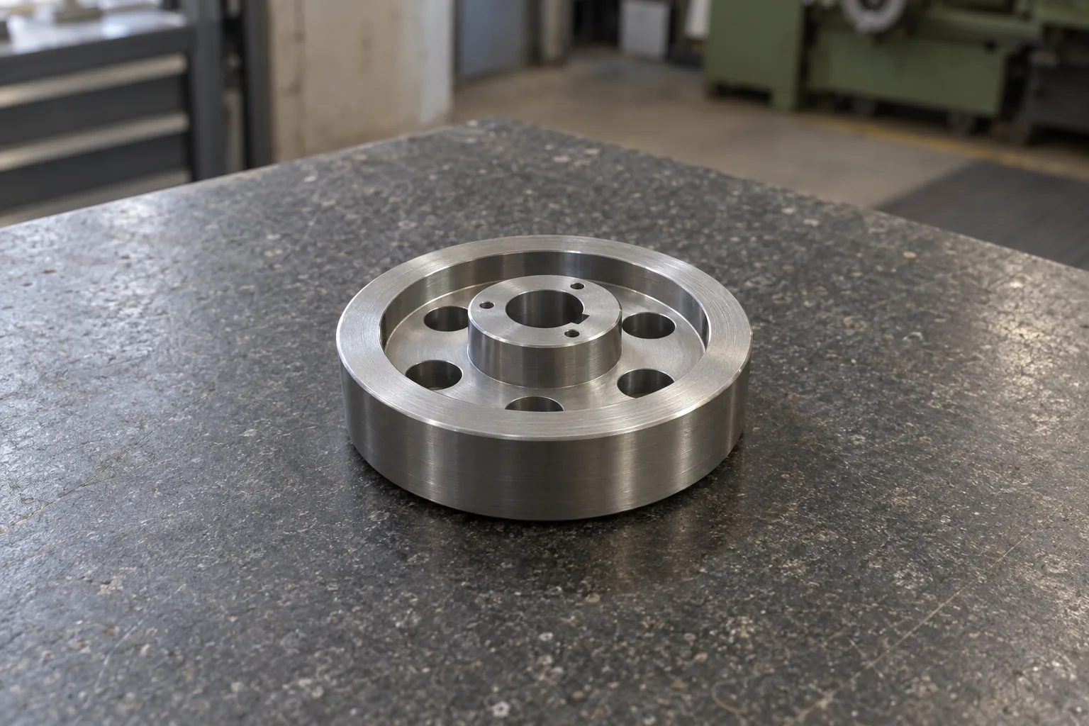
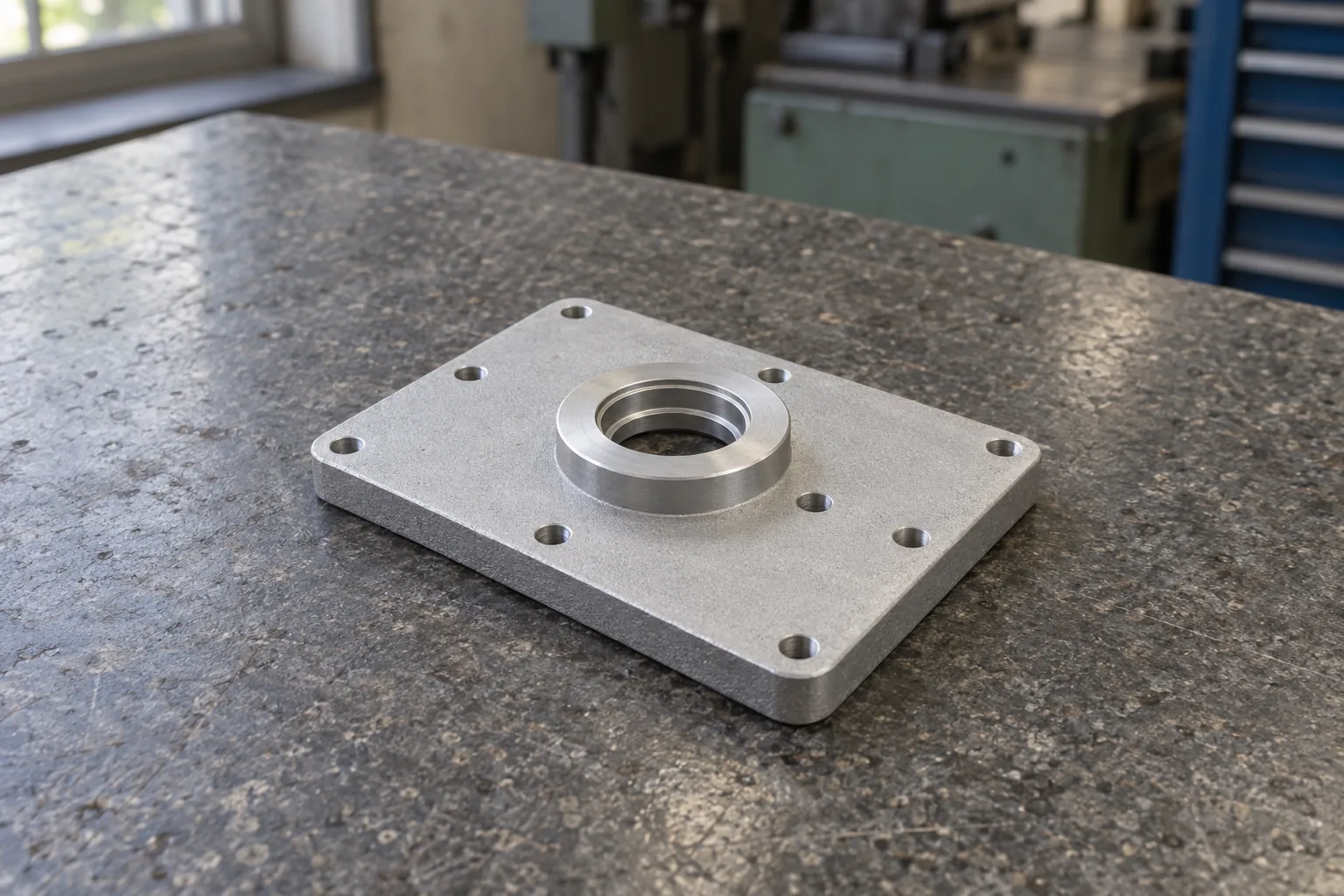
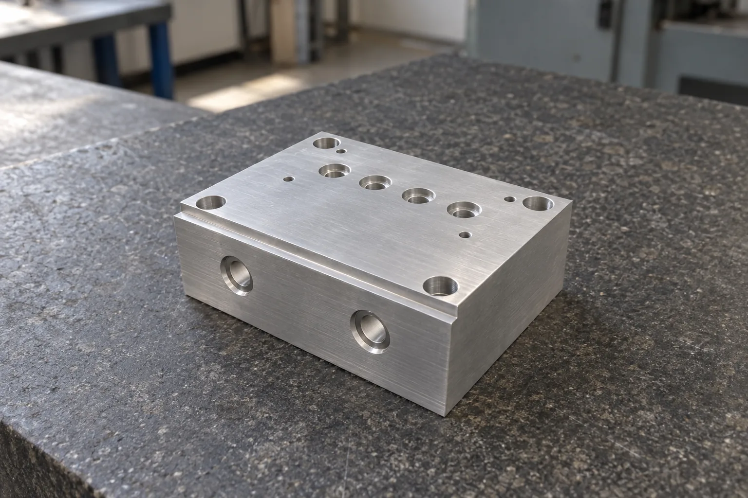
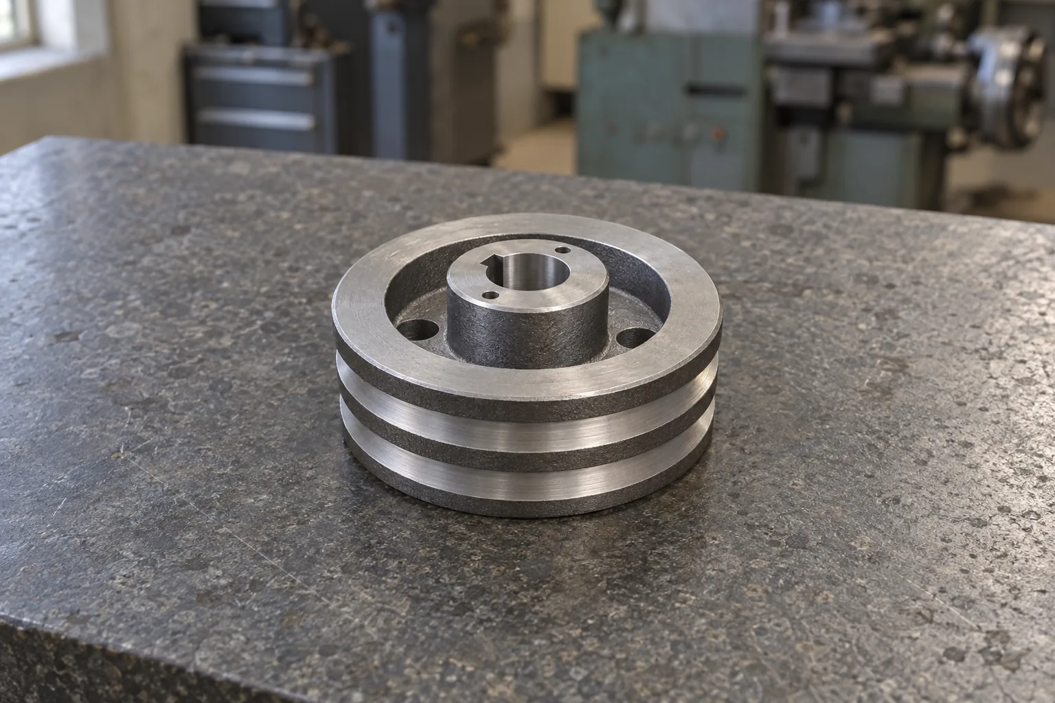
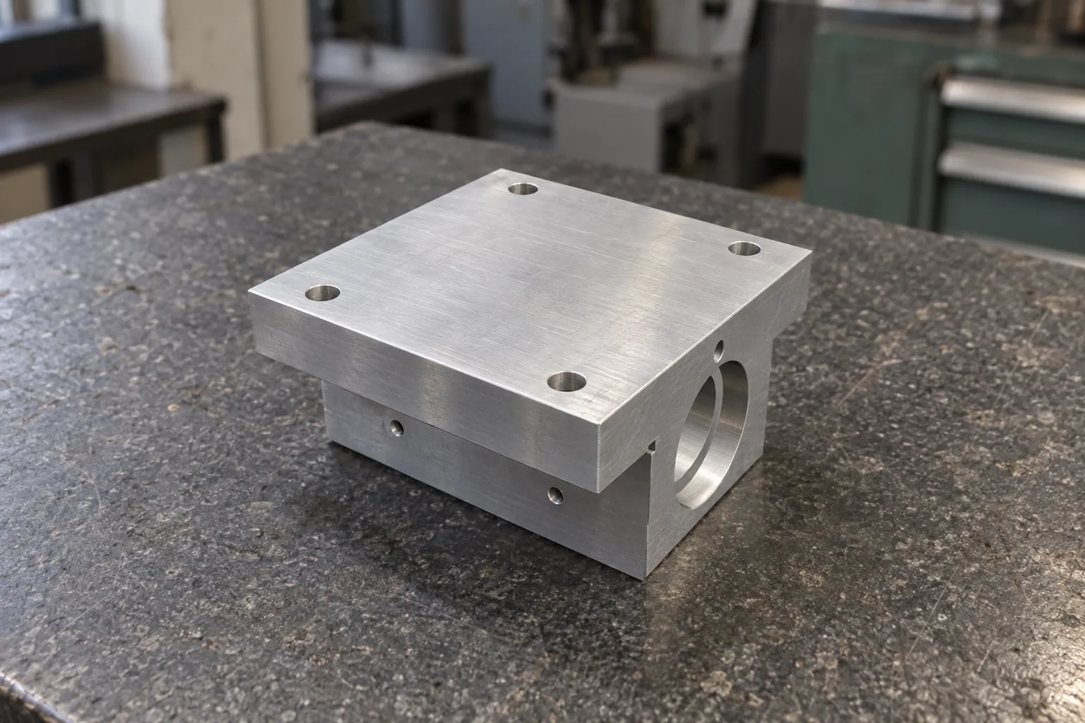
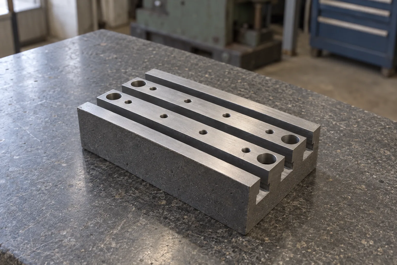
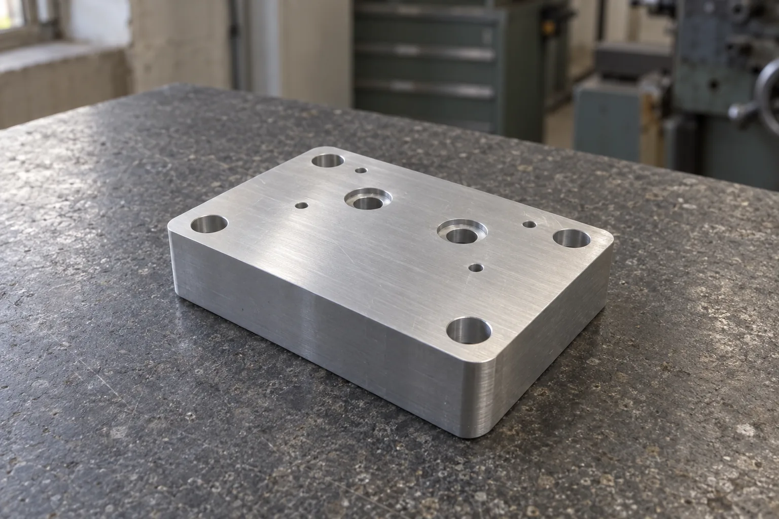
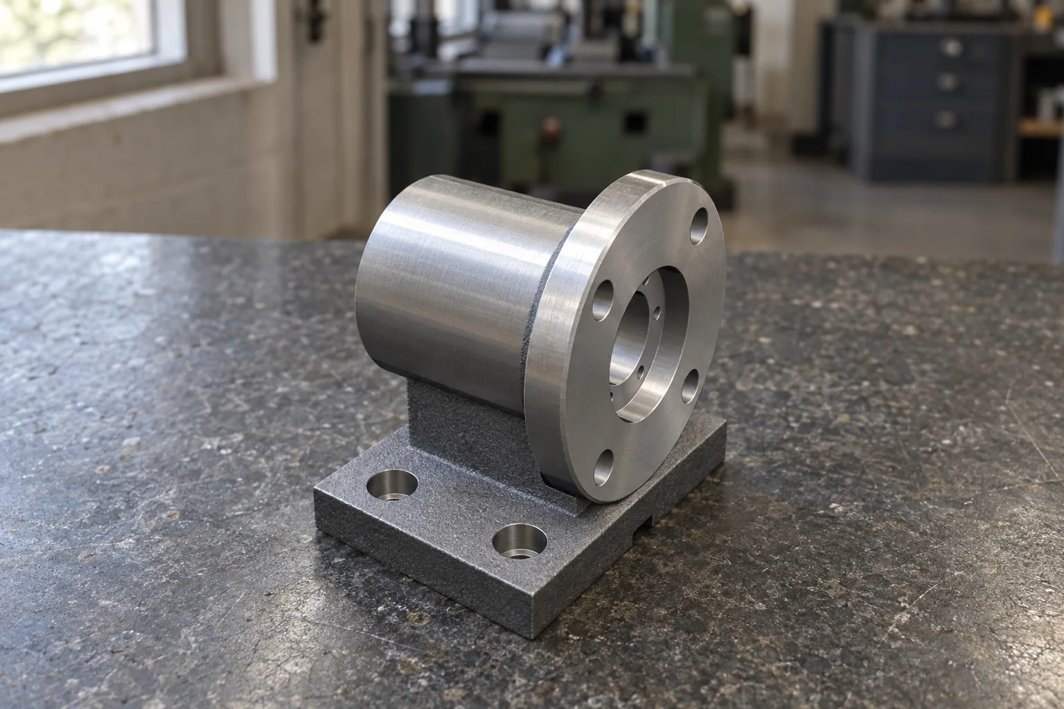
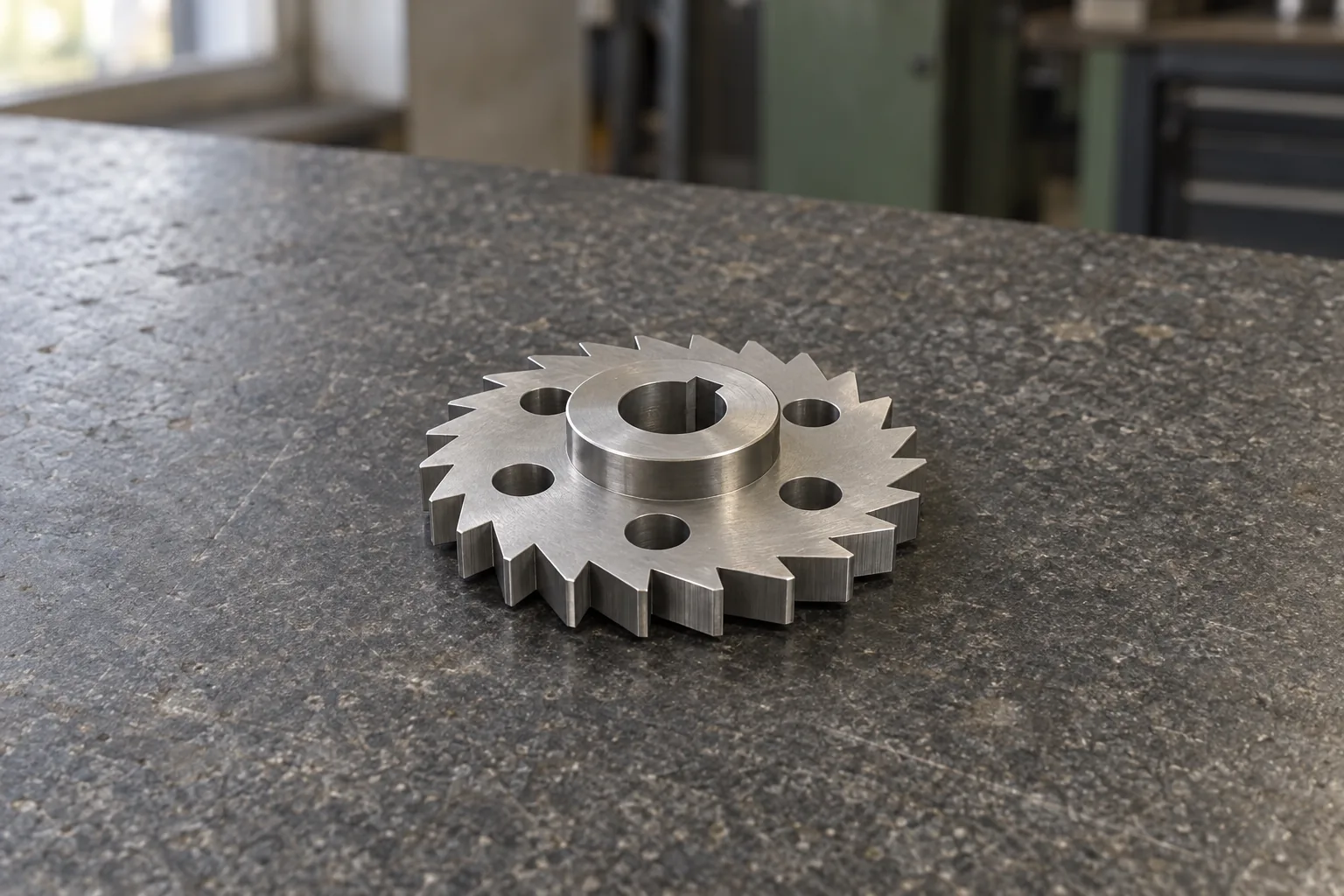
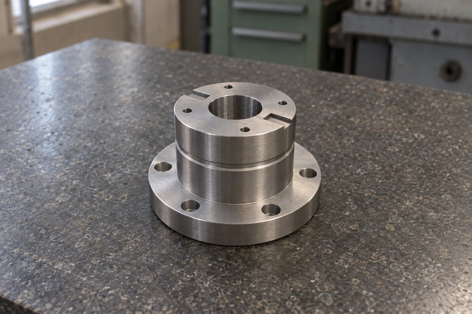
Gearbox cover with gasket groove
From the benchmark · TP-C021
7 views with section and detail · internal geometry · a correct reader reads it
A synthetic, company-owned test part from TruePart's fifty-part benchmark, pictured as its drawing specifies it. It has not been built by TruePart or made in a shop.
Drawing to CAD: the questions engineers ask first.
Which drawings can TruePart turn into CAD today?
Native vector PDF with a text layer: one sheet, one part, millimetres, up to 10 MB. Scanned, raster or multi-sheet drawings are stopped, not guessed at.
Which parts can it build?
One part family in the Technical Preview. It builds one family: a rectangular plate with one centered through bore and one centered rectangular pattern of through holes; sharp, chamfered or rounded corners. Any other part shape is stopped as outside the current scope. Complex multi-view part families are in development and not yet offered.
What happens when the drawing does not state a value?
TruePart asks one targeted question and builds nothing until it is answered. Plain linear dimensions and positions shown only by centerlines are asked today, never guessed.
What does verified mean here?
Verification measures the envelope, volume, hole count, and each hole’s position and diameter against the approved specification. It does not check tolerance bands, material or manufacturability, and a misread callout still needs your review.
Does AI read the drawing?
No. Current public demo: deterministic drawing reader. AI-assisted interpretation: in evaluation, not enabled in this preview.
Further reading
See drawing to CAD on the demo drawing.
The home page follows a sample drawing through each stage. Pilot participants bring their own drawings.