

AI CAD, explained for engineering drawings.
TruePart is AI CAD for engineering drawings: it starts from a 2D drawing you already have, not from a text prompt, and turns it into structured requirements and verifiable CAD, exported as STEP and STL. The Technical Preview reads native vector PDFs of one part on one sheet and builds one part family: rectangular plates with a centered bore and a hole pattern. AI interpretation is not enabled.
Technical Preview · Currently supporting select part families · Current public demo: deterministic drawing reader · AI-assisted interpretation: in evaluation, not enabled · Complex multi-view drawings: in development
What AI CAD means.
AI CAD is a loose name for software in which a learned model does part of the CAD work. Sorted by what you give the tool and what it returns, four kinds cover most of what is sold under it.
Text-to-CAD
- You give it
- A description in words, sometimes with a sketch or an image.
- It returns
- A generated part: a CAD script or feature sequence, a solid, or a mesh.
- Check first
- Every value the prompt did not state was chosen by the tool.
AI assistants in CAD
- You give it
- Questions and commands inside a CAD system you already use.
- It returns
- Answers, suggested features and constraints, automated steps and macros.
- Check first
- What leaves your network, and whether your models are used to train it.
Generative models for CAD
- You give it
- A partial model, a shape description or design constraints.
- It returns
- Generated or completed geometry, sometimes editable features; often called neural CAD or AI-native CAD.
- Check first
- The dimensions that matter still need a requirement to be checked against.
Drawing-to-CAD
- You give it
- An existing 2D engineering drawing, usually a PDF.
- It returns
- A 3D model of the part the drawing defines, exchanged as STEP.
- Check first
- Each value traced to the drawing, and every gap asked about, never filled.
Drawing in, CAD out, checked against the approved spec.
TruePart is the drawing-to-CAD kind of AI CAD, built so that a model only proposes and never decides. In the Technical Preview no learned model runs: a deterministic drawing reader reads the sheet. The drawing defines the part, so the software's job is to read it, not to invent: what the drawing states becomes a requirement, and what it does not state becomes a question.
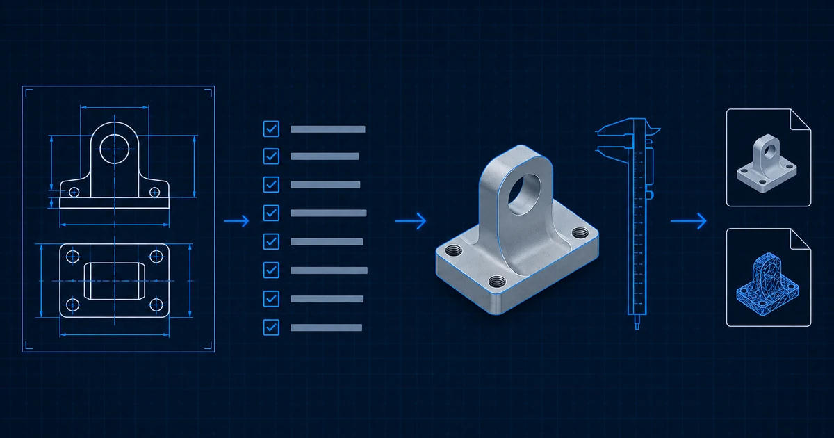
Drawing
A native vector PDF: one part on one sheet, in millimetres, up to 10 MB. Its text layer is kept with exact positions.
Structured requirements
Callouts and title-block fields become requirements, each linked to its place on the sheet. A value the drawing does not prove becomes one question, and nothing is built until it is answered.
Checked CAD
The approved specification becomes a typed plan, and a deterministic CAD engine builds the B-rep solid: no model writes geometry code. The solid is measured against the specification before export.
STEP and STL
The exact solid as STEP for CAD, CAM and inspection, and a mesh of it as STL for printing. Tolerance bands, material and manufacturability are not checked.
A worked example: a cast aluminium gearbox cover drawn in three views and a section, with a bolt flange, two bearing bores, ribs, pockets, fillets and tapped holes. Each callout becomes a requirement, and each value the views leave open becomes a question before anything is built. Complex parts: in development. Today TruePart builds one part family: rectangular plates with a centered bore and a hole pattern.
What is live today, and what is not.
Every TruePart capability is stated in one of four tiers, with what is built apart from what is enabled. Only the first tier is available to customers.
The Technical Preview
Production-verified
Native vector PDF drawings of one part on one sheet, in millimetres. It builds one part family, rectangular mounting plates with a centered bore and a hole pattern: the current demo's scope.
- Built, tested, merged
- Built, tested and merged.
- Deployed, enabled, production-verified
- Deployed, enabled for customers and production-verified.
A multi-view bracket path
Implemented, not enabled
A stepped bracket drawn in several views and a section, taken from a synthetic, company-authored drawing to a STEP file in internal tests, with the readers it uses. Internal only: customers cannot use it.
- Built, tested, merged
- Built, tested in internal tests and merged.
- Deployed, enabled, production-verified
- Not enabled for customers and not production-verified.
Groundwork for complex part families
In development
Work on open branches, starting with integrity fixes to the internal multi-view path. Each family is to be measured on held-out drawings before it is offered. No held-out results are published yet.
- Built, tested, merged
- Not merged: work on open branches.
- Deployed, enabled, production-verified
- Not deployed, not enabled, not production-verified.
Complex part families
Roadmap
Family by family: a bracket or housing block with features on several faces, a turned flange, a stepped shaft and a bearing housing, with sections, diameters and datums read from the drawing. Planned, not built.
- Built, tested, merged
- Not built.
- Deployed, enabled, production-verified
- Not deployed, not enabled, not production-verified.
The guides and comparisons explain AI CAD, drawing to CAD and PDF to STEP in more depth, and say where a person, or any software, has to stop and ask.
AI CAD: the questions engineers ask first.
What is AI CAD?
Software in which a learned model does part of the CAD work: generating a part from a description (text-to-CAD), assisting inside a CAD system, generating or completing CAD geometry, or rebuilding a part from an existing drawing (drawing-to-CAD). TruePart is the drawing-to-CAD kind, built so that a model only proposes and never decides; in the Technical Preview no learned model runs. Current public demo: deterministic drawing reader. AI-assisted interpretation: in evaluation, not enabled in this preview.
Is TruePart a text-to-CAD tool?
No. TruePart starts from a 2D engineering drawing you already have, not from a text prompt. Text, photo and sketch input are not in the Technical Preview.
Does TruePart use AI to read drawings today?
Not in the Technical Preview. Current public demo: deterministic drawing reader. AI-assisted interpretation: in evaluation, not enabled in this preview. When AI-assisted interpretation is enabled, it will return candidates and questions, never geometry or code.
Which drawings and parts work today?
Native vector PDF with a text layer: one sheet, one part, millimetres, up to 10 MB. One part family is built: rectangular plates with a centered bore and a hole pattern. Scanned, raster or multi-sheet drawings are stopped, not guessed at. Complex multi-view part families are in development and not yet offered.
What does verified mean here?
Verification measures the envelope, volume, hole count, and each hole’s position and diameter against the approved specification. It does not check tolerance bands, material or manufacturability, and a misread callout still needs your review.
Are my drawings used to train AI models?
No, not by default. Customer engineering data is not used to train shared models unless the customer explicitly chooses otherwise. Current public demo: deterministic drawing reader. AI-assisted interpretation: in evaluation, not enabled in this preview.
Further reading
Try AI CAD on an engineering drawing.
TruePart is in Technical Preview. Today TruePart builds one part family: rectangular plates with a centered bore and a hole pattern. Current public demo: deterministic drawing reader. AI-assisted interpretation: in evaluation, not enabled in this preview. Get started to see how access works today, or read how the pipeline works first.