

TruePart.aiTruePart.ai

AI CAD for engineering drawings.

From the drawing you already have to STEP and STL, checked against the approved spec.

Technical Preview · One part family live · Current public demo: deterministic drawing reader · AI-assisted interpretation: in evaluation, not yet enabled · Complex multi-view drawings: in development

120.00 ±0.0580.0060.00100.0012.004× Ø6.60 THRUØ0.10ABØ24.00 H7CBORE Ø32.00DP 4.004× R8.00Ra 1.6ABTITLEDWG NOREVMATERIALFINISHSCALEUNITSTOLERANCES UNLESS NOTEDDRAWNSHEETNOTESMOUNTING PLATE, SENSORTP-4471-02CAL 6061-T6ANODIZE II BLK1:1MMX.X ±0.1 X.XX ±0.05 ANG ±0.5°JMR 03-141/1INTERPRET PER ASME Y14.5-2018THIRD ANGLE PROJECTION1. ALL DIMENSIONS IN MM AFTER FINISH.2. BREAK SHARP EDGES 0.2 MAX. DEBURR ALL.3. ANODIZE PER MIL-A-8625 TYPE II CL 2 BLACK.DIM.01 · 120.00 ±0.05GDT.01 · ⌖ Ø0.10 A BBORE Ø24.00 H7DATUM AHOLE ×4TITLE BLOCK · 9 FIELDSNOTES ×3 → 3 SPECS12.00Ø24.00 H7XYZ
TP-4471-02_revC.pdf · Sheet 1/1Step 1 of 3 · source drawing
Illustration · sample drawingSource
FileTP-4471-02_revC.pdf
ViewsFront, side · third angle
Content11 dims · 1 FCF · 3 notes
StateNo CAD · no model · no data

Live in the Technical Preview: native vector PDF drawings, in millimetres. What it cannot read, it stops and says so.

PDFNative vector
ScansStopped, not guessed
Multi-sheetStopped, not guessed
One partOne sheet per drawing
MillimetresMetric drawings
PlatesCentered bore, hole pattern
Up to 10 MBPer drawing
STEP · STLOne solid, two formats

What is live, and what is not yet.

  • The Technical Preview

    Production-verified

    Native vector PDF drawings of one part on one sheet, in millimetres. It builds one part family, rectangular mounting plates with a centered bore and a hole pattern: the current demo's scope.

  • A multi-view bracket path

    Implemented, not enabled

    A stepped bracket drawn in several views and a section, taken from a synthetic, company-authored drawing to a STEP file in internal tests, with the readers it uses. Internal only: customers cannot use it.

  • Groundwork for complex part families

    In development

    Work on open branches, starting with integrity fixes to the internal multi-view path. Each family is to be measured on held-out drawings before it is offered. No held-out results are published yet.

  • Complex part families

    Roadmap

    Family by family: a bracket or housing block with features on several faces, a turned flange, a stepped shaft and a bearing housing, with sections, diameters and datums read from the drawing. Planned, not built.

See a complex drawing (a conceptual illustration, in development)

Every part begins as a drawing. Then it is read again for quoting, again for CAM, again for inspection and again for ERP. By different people, by hand, each time a new chance to get it wrong. TruePart reads it once.

SourceDrawing · PDFThe authority
QuotingFeatures, finishRe-keyed by hand
CAMGeometry, stockRe-keyed by hand
InspectionDims, FCFs, datumsRe-keyed by hand
ERP · PLMMaterial, revisionRe-keyed by hand

One drawing, read end to end.

Illustration · a sample drawing, not a TruePart result
1Part on one sheet per drawing in the live preview; complex multi-view drawings are in development
10 MBLargest drawing accepted: one native vector PDF, in millimetres
2Formats from one solid: STEP and STL
0Values guessed: what the drawing leaves open is asked for

One pipeline, from sheet to verified solid.

Each stage produces something a person can inspect. Nothing is guessed: what the drawing leaves open is asked for. Shown on a sample drawing: an illustration, not a TruePart result.

Ingest

A native vector PDF: the file is hashed, its page rendered, and its text kept with exact positions. Scanned or multi-sheet drawings are stopped, not guessed at.

In · native vector PDF · mm
Ø24.00 H7CBORE Ø32.00DP 4.00BCALLOUT.02FEATURE.BOREDATUM B

Recognize

Dimensions, hole callouts, notes and title block fields, read from the PDF's own text, each with its exact place on the sheet.

Out · values with sheet positions
Part     TP-4471-02 · C
├─ Bore  Ø24.00 H7
│  └─ CBORE Ø32 × 4
├─ Hole  4× Ø6.60
│  └─ ⌖ Ø0.10 | A | B
├─ Datum A · B
└─ Spec  6061-T6 · AN-II

Structure

What the drawing states becomes the part's specification; what it leaves open is asked for and recorded. Conflicts surface instead of hiding.

Out · approved specification
5/5
Envelope Pass
Volume Pass
Hole count Pass
Hole positions Pass

Verify

One B-rep solid, measured against the approved specification: envelope, volume, hole count, and each hole at planned position and diameter. Not tolerance bands, material or manufacturability.

Out · STEP · STL

Reads what the drawing states.

From the PDF's own text, not OCR on a picture. Every value keeps its exact place on the sheet, and what the drawing leaves open is asked for, not guessed.

Diameter, radius, thread and chamfer callouts read from the PDF's own text, each with its exact place on the sheet. Plain linear dimensions are asked, not guessed. Tolerances are recorded as written. The preview does not verify tolerance bands.

Illustration · sample TP-4471-02 · Sheet 1/111 dims · with sheet positions
120.00 ±0.0580.0060.00100.0012.004× Ø6.60 THRUØ0.10ABØ24.00 H7CBORE Ø32.00DP 4.004× R8.00Ra 1.6ABTITLEDWG NOREVMATERIALFINISHSCALEUNITSTOLERANCES UNLESS NOTEDDRAWNSHEETNOTESMOUNTING PLATE, SENSORTP-4471-02CAL 6061-T6ANODIZE II BLK1:1MMX.X ±0.1 X.XX ±0.05 ANG ±0.5°JMR 03-141/1INTERPRET PER ASME Y14.5-2018THIRD ANGLE PROJECTION1. ALL DIMENSIONS IN MM AFTER FINISH.2. BREAK SHARP EDGES 0.2 MAX. DEBURR ALL.3. ANODIZE PER MIL-A-8625 TYPE II CL 2 BLACK.DIM.01 · 120.00 ±0.05DIM.04 · 100.00 ±0.05DIM.05 · 12.00R8.00 ×4GDT.01 · ⌖ Ø0.10 A BDATUM ADATUM BHOLE ×4TITLE BLOCK · 9 FIELDSNOTES ×3 → 3 SPECSFINISH · Ra 1.6REV B → C · SPACING 98.00 → 100.00REV B → C · FINISH CLR → BLKREV C · NOTE 3 ADDED
Overall width120.00 ±0.05
Limits119.95 / 120.05
Bound toPlate envelope

Trace every value to the sheet.

An interactive illustration with sample data, not the product's own screen: select any value to see where it came from on the sheet. What the Technical Preview verifies and exports is under Verification and Outputs.

TruePartSensor assembly / TP-4471-02 · Rev CVerified
120.00 ±0.0580.0060.00100.0012.004× Ø6.60 THRUØ0.10ABØ24.00 H7CBORE Ø32.00DP 4.004× R8.00Ra 1.6ABTITLEDWG NOREVMATERIALFINISHSCALEUNITSTOLERANCES UNLESS NOTEDDRAWNSHEETNOTESMOUNTING PLATE, SENSORTP-4471-02CAL 6061-T6ANODIZE II BLK1:1MMX.X ±0.1 X.XX ±0.05 ANG ±0.5°JMR 03-141/1INTERPRET PER ASME Y14.5-2018THIRD ANGLE PROJECTION1. ALL DIMENSIONS IN MM AFTER FINISH.2. BREAK SHARP EDGES 0.2 MAX. DEBURR ALL.3. ANODIZE PER MIL-A-8625 TYPE II CL 2 BLACK.DIM.01 · 120.00 ±0.05DIM.02–03DIM.04 · 100.00 ±0.05DIM.05 · 12.004× R8.00REV B → C · HOLE SPACING 98.00 → 100.00REV B → C · FINISH CLR → BLKREV C · NOTE 3 ADDEDREVIEW · NOTE 2 · EDGE BREAK 0.2 MAX BELOW SHOP DEFAULT 0.5Callout.02 · bore Ø24.00 H7
Sheet 1/1 · 100%
X 262.00 Y 110.00
FeatureNominalToleranceSrcRead
Selected · BoreApproved
Nominal · tolerance
Ø24.00 H7
Limits
+0.021 / 0 · ISO 286
Source
Sheet 1 · Front · (262, 110)
Bound to
CBORE Ø32.00 DP 4.00
11 dimensions read5 holes checked6 notes1 item for reviewSample dataSTEP and STL ready

One solid. Open formats.

STEP and STL from the same solid, the report of what was verified, and the drawing it came from. Nobody remodels the part from the PDF. The panels illustrate a sample drawing's output, not a TruePart result.

STEP solid model

One B-rep solid, built from what the drawing states and what you confirm, measured against the approved specification. Opens in any CAD or CAM tool.

Ø24.00 H7

STL from the same solid

The same solid as an STL mesh, for viewers, quoting conversations and 3D printing.

SIZE120 × 80 × 12 mmenvelope
BOREØ24.00 · centeredchecked
HOLES4× Ø6.60 THRUchecked
FROMThe STEP solidsame B-rep
FILETP-4471-02.stlmesh

A verification report

What was measured and the result: envelope, volume, hole count, and each hole at planned position and diameter, at nominal dimensions.

1EnvelopePass
2VolumePass
3Hole count · 5Pass
4Hole positionsPass
5Hole diametersPass
Not checked: tolerance bands, material

The drawing it came from

The source PDF stays with the part, identified by its hash, with every value tied to its place on the sheet.

{
  "drawing": "TP-4471-02_revC.pdf",
  "sha256": "9f2c…41ab",
  "pdf": "native vector", "sheets": 1,
  "units": "mm",
  "bore": { "sheet": 1, "x": 266, "y": 117 }
}

Built to be checked.

Engineers don't trust what they can't verify. Every value can be traced to the sheet, and every check says what it measured. Illustrated on a sample drawing, not a measured result: fits such as H7, counterbores, GD&T, material and finish are not verified.

Illustration · sample drawing · front viewØ24.00 H7CBORE Ø32.00DP 4.00BCallout.02 · X 266.00 Y 117.00 · leader → feature.bore
Extracted valueØ24.00 H7
DiameterPass
FeatureBore, through · centered on the plate
Checkedposition and diameter, at nominal
SourceTP-4471-02_revC.pdf · sheet 1 · (266, 117)
ReviewFor review by a qualified person

Every value points back to the sheet.

Each dimension and note keeps its sheet and its exact place on it.

Nothing is guessed.

What the drawing leaves open is asked for and recorded. Output is for review by a qualified person.

Checked against the specification.

Envelope, volume, hole count, and each hole at planned position and diameter.

Two formats, one model.

STEP and STL come from the same B-rep solid.

Deployment, data handling and retention: see Security

Fifty complex test parts, in our evaluation corpus.

TruePart's evaluation corpus: fifty authored mechanical parts, each a STEP solid, a dimensioned drawing projected from that solid, and exact ground truth. Every drawing carries a challenge (fully specified, partial, internal geometry, several views, datums, a missing or conflicting dimension, an ambiguous or non-inferable one) and the outcome a correct reader must reach: read it, or ask.
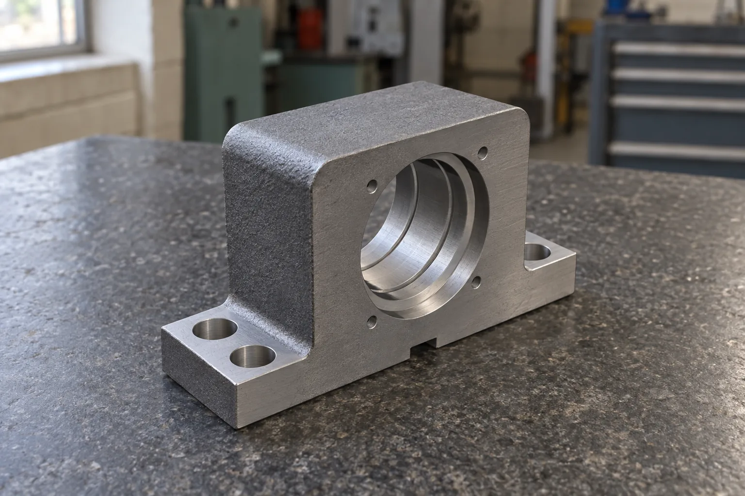
  • A grey cast-iron pillow block bearing housing on a granite surface plate: a bored body with two internal grooves on two counterbored feet

    Pillow block bearing housing

    TP-C006

    6 views with section A-A · internal geometry
    Pillow block bearing housing

    TP-C006 · synthetic corpus drawing

    Synthetic corpus drawing TP-C006: Pillow block bearing housing, 6 views with section A-A · internal geometry

    6 views with section A-A · internal geometry

    A synthetic, company-owned test part from TruePart's fifty-part benchmark, pictured as its drawing specifies it. It has not been built by TruePart or made in a shop.

    Open the drawing file ↗
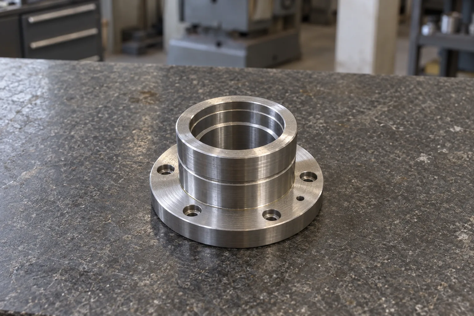
  • A turned steel flanged bearing cartridge on a granite surface plate: a grooved body on a flange with counterbored bolt holes

    Flanged bearing cartridge

    TP-C002

    7 views with section and detail · internal geometry
    Flanged bearing cartridge

    TP-C002 · synthetic corpus drawing

    Synthetic corpus drawing TP-C002: Flanged bearing cartridge, 7 views with section and detail · internal geometry

    7 views with section and detail · internal geometry

    A synthetic, company-owned test part from TruePart's fifty-part benchmark, pictured as its drawing specifies it. It has not been built by TruePart or made in a shop.

    Open the drawing file ↗
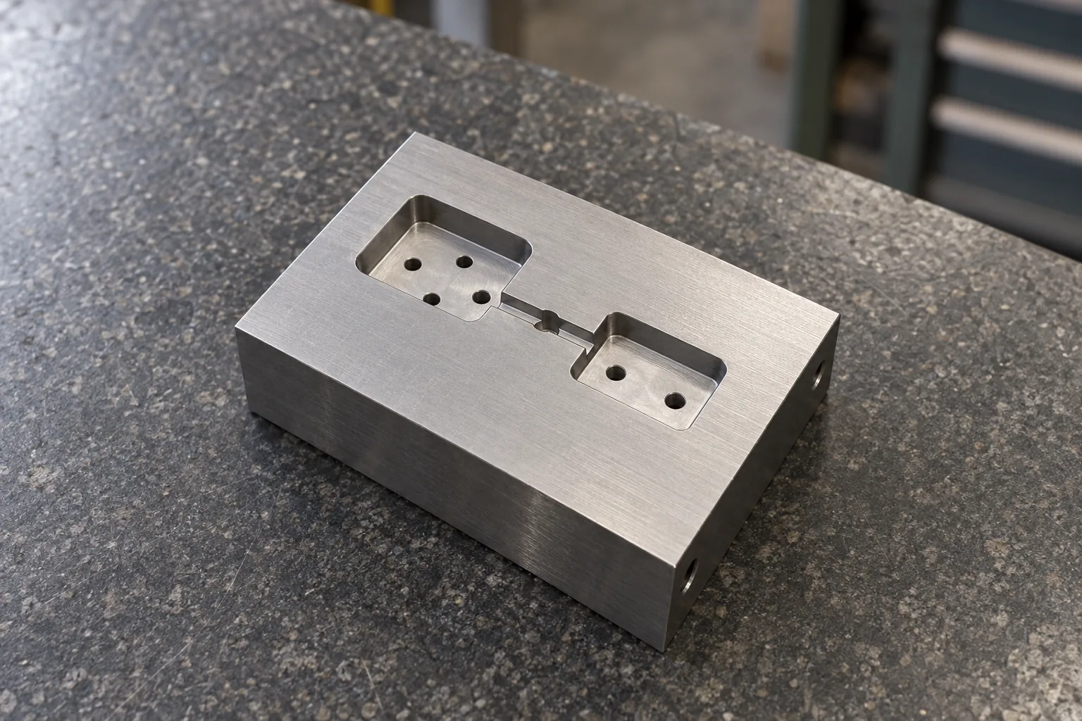
  • A milled steel mould insert block on a granite surface plate: two cavities joined by a runner, with ejector holes in their floors

    Two-cavity mould insert

    TP-C032

    6 views with section A-A · non-inferable value

    Two-cavity mould insert

    TP-C032 · synthetic corpus drawing

    Synthetic corpus drawing TP-C032: Two-cavity mould insert, 6 views with section A-A · non-inferable value

    6 views with section A-A · non-inferable value

    A synthetic, company-owned test part from TruePart's fifty-part benchmark, pictured as its drawing specifies it. It has not been built by TruePart or made in a shop.

    Open the drawing file ↗

Each part is pictured as its drawing specifies it. Synthetic, company-owned test drawings, marked not for manufacture. None of these parts has been built by TruePart or made in a shop; the live pilot reads one part family today. No results on it are published yet.

Questions, answered.

A STEP and an STL of one solid, built from what the drawing states and what you confirm, measured against the approved specification, with a verification report. In the Technical Preview: native vector PDF drawings of one part on one sheet, in millimetres, for rectangular plates with a centered bore and a hole pattern.

See TruePart read your own drawings.

Tell us about your parts and where the models need to go. We walk through what TruePart reads from your own drawings, value by value, with your engineers on the call.

Tell us about your partsDrawing types, volumes and the systems downstream.
Live walkthroughYour drawings through TruePart, checked value by value.
Pilot on your workflowYour team works in TruePart with your own parts loaded.

Book a demo

We use what you send to read and answer this message and to limit abuse; see Privacy. Please do not include confidential information, drawings, or personal data of others.

Your privacy choices

We use analytics cookies to see how people use TruePart. Advertising stays off unless you allow it. Privacy